We are glad to share with you about the results of our work, company news,and give you timely developments and personnel appointment and removal conditions.
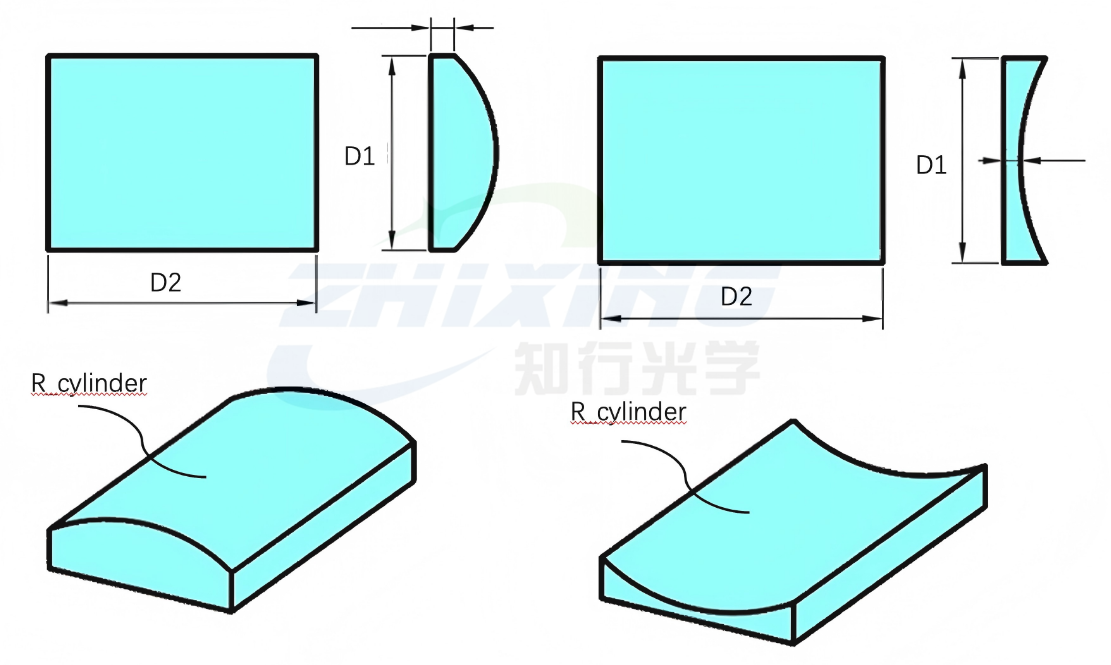
Cylindrical mirrors are widely used in laser shaping, spectroscopic instruments, photolithography, and imaging optics. High-precision surface shape detection of cylindrical mirrors largely relies on cylindrical CGHs (computational holographic elements) for null-point interferometry detection. Cylindrical mirrors are divided into concave and convex types, and the selection constraints for CGHs differ between them. Incorrect selection can lead to problems such as incomplete wavefront coverage, inability to position the optical path, and failure to complete null-point detection. It can also directly result in incorrect CGH procurement, wasting time and money for the company. Today, we break down the complete selection logic for cylindrical CGHs to help you avoid common pitfalls.
Modern CGH Null Correctors provide a practical approach by combining computer-designed diffraction technology with precision optical manufacturing. They bridge the gap between theoretical optical design and real-world production inspection, allowing engineers to evaluate complex surfaces with greater confidence.
Peter Drucker, the father of modern management, famously said a business and engineering rule: "If you can't measure it, you can't improve it." In the field of precision optical manufacturing, this rule is equally cold and ruthless: in the aspherical surface processing industry, if you cannot perform precise and efficient metrology and measurement, you simply cannot quickly and effectively improve the aspherical surface processing technology.
As fields such as semiconductor inspection, industrial vision, and high-end microscopic imaging continue to advance towards higher resolutions, lens performance verification is facing new challenges. Many lenses, after wavefront testing during the R&D phase, exhibit excellent performance indicators; however, when actually installed in CCD or CMOS systems, the actual imaging results often fall short of expectations. Why? Because the final performance of a lens depends not only on the optical design itself but also on whether the entire optoelectronic system can truly "see clearly." This is precisely the key value of the USAF Resolution Target.
In the lens research, development, production, and acceptance processes, a common problem arises: how to quickly determine whether a lens can "see clearly"?
One of the most classic and commonly used methods is to use:
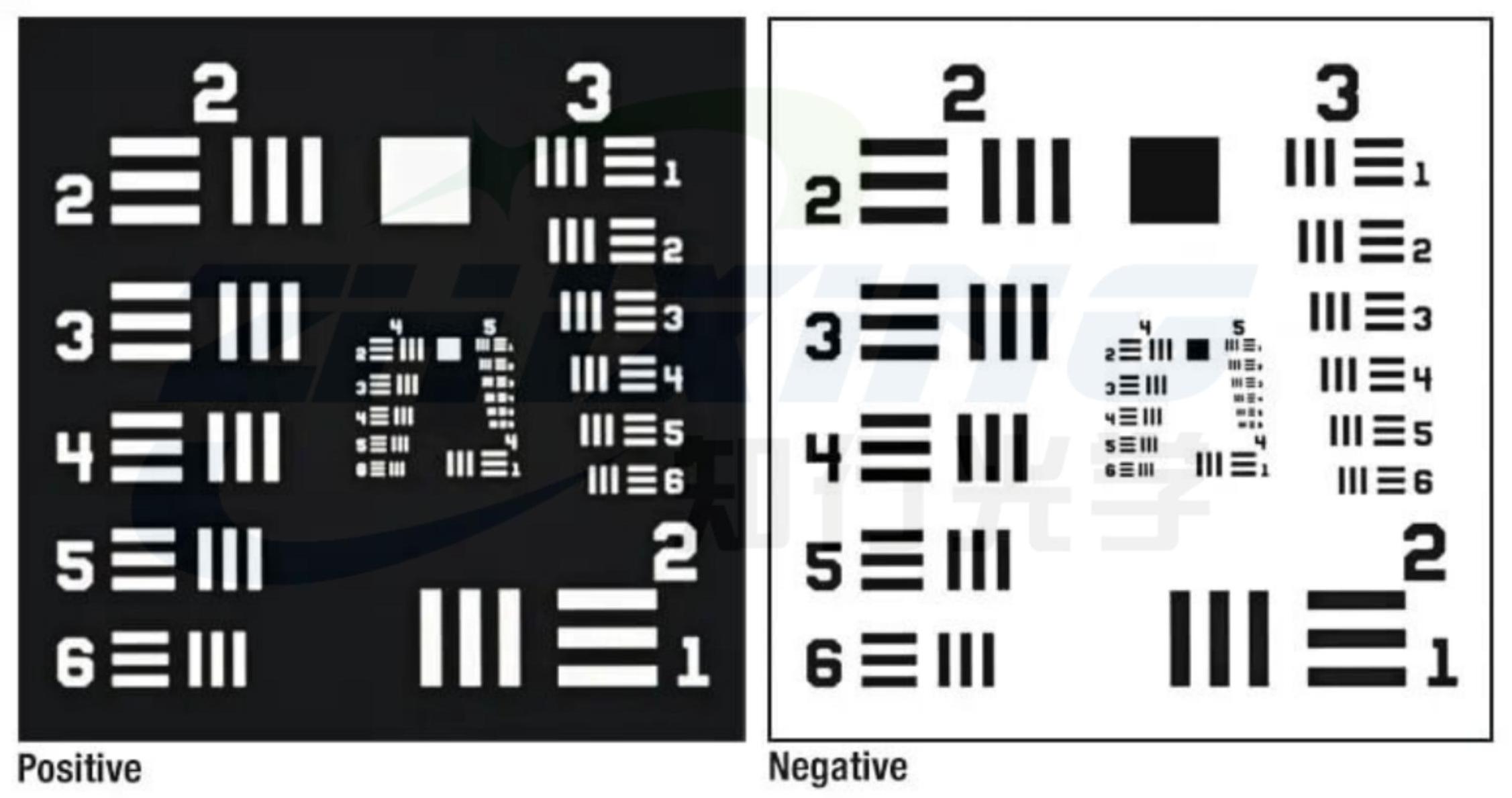
The USAF 1951 Resolution Chart (US Military Standard Resolution Chart).
It is a basic testing tool that almost all optical laboratories, lens manufacturers, and industrial vision companies are equipped with. However, many customers still have several questions after receiving the resolution chart:
How to use it correctly?
How to interpret the test results?
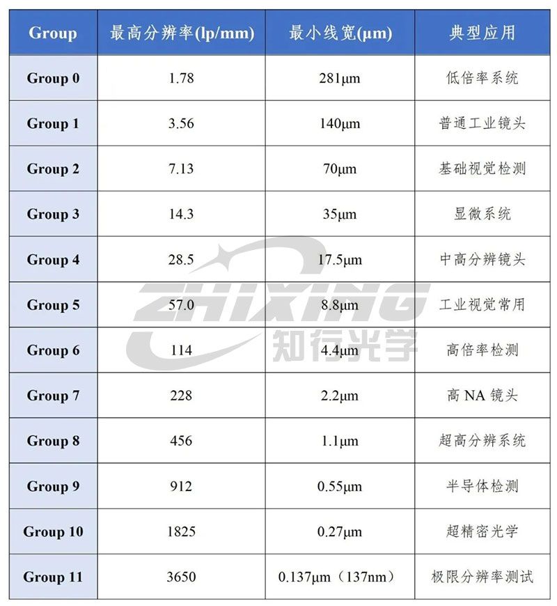
How to determine lens resolution?
What do Group and Element mean?
This article will provide a quick overview.
In the development of high-end optical systems, a core question frequently arises:
How to accurately evaluate the imaging quality of a system?
Currently, the two most commonly used methods are:
◆ Wavefront testing
◆ MTF (Modulation Transfer Function) testing
Both can evaluate system performance, but their focuses are completely different.
Simply put:
Wavefront testing identifies "where the system has problems"; MTF testing assesses "the quality of the final image."
Understanding the differences between the two is crucial for choosing the correct testing method.
We use cookies to offer you a better browsing experience, analyze site traffic and personalize content. By using this site, you agree to our use of cookies.Privacy Policy

 20 2026-08
  29 2026-07
  29 2026-06
  26 2026-06
  17 2026-06
  15 2026-06